Electrode wear in air and oxygen plasma
How to tell good electrode wear from bad and improve system performance
Electrodes for high power plasma cutting systems are highly engineered consumable parts, similar in design, material, and function to an automotive spark plug. Like spark plugs, electrodes emit high voltage electricity in a high temperature environment. The materials must withstand plasma temperature arc emissions, endure swirling high velocity gas jets, and provide a hermetic seal to high-pressure gases and fluids. The electrode, like a spark plug, is the hardest working part in the system.
A good mechanic can tell a lot about the health of a combustion engine by looking at the spark plugs. A trained plasma technician can do the same for a plasma system if he learns how to inspect the electrode, understands normal wear patterns, and knows how to spot signs of trouble.
The electrode carries the DC power from the plasma power supply to the metal plate. It is typically comprised of a copper or copper/silver composite holder that contains an emissive element of hafnium-a high melting point metal that will sustain an arc in air and oxygen cutting environments. The emitting element is slowly eroded away by the heat of the arc, and the high velocity plasma gas stream. Most of this wear occurs at the start and stop of a cut when the molten hafnium material quickly heats up and cools down, melting then re-solidifying.
During normal wear a small concave pit is formed in the end of the part that steadily wears away, a few thousandths of an inch at a time, to a depth of .040" to .125" deep depending on the torch and consumable design and materials. (See table below). When the pit becomes too deep, the arc attaches to the holder material and melts it. The electrode "fails" when it will no longer initiate and sustain an arc. If molten material from the electrode is deposited downstream into the bore of the nozzle it causes a "blowout"-catastrophic failure of both the electrode and nozzle.
| Plasma arc cutting (PAC) system | Copper electrodes inches of wear | Copper / silver composites inches of wear |
| High precision PAC (oxygen plasma) |
.030"-.050" | .060"-.080" |
| Water injection PAC (oxygen plasma) |
.040"-.080" | .100"-.140" |
| Conventional dual gas PAC (oxygen plasma) | .040"-.080" | .100"-.140" |
| Conventional dual gas PAC | .090"-.120" | .100"-.140" |
Electrode wear visual guide
Normal parts life for state-of-the-art oxygen plasma systems is 1-2 hours of arc-on time and 200-300 pierces. Air systems can typically achieve twice this life, 400-600 starts, because the nitrogen component of air makes it less reactive with the electrodes. Oxygen plasma systems with inert start gases and current ramping can reach 1000 or more starts before an electrode change is necessary.
|
Figure 1
|
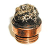
New conditionFigure 1 shows a picture of a new electrode. In this example the electrode is a welded copper silver composite design with silver on the forward portion of the electrode and copper on the back end. In the center of the part is the unused hafnium element. |
|
Figure 2
|
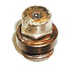
Normal wearFigure 2 shows an electrode with a normal wear pattern. The hafnium pit is well centered and uniform in shape, indicating good alignment of consumables and a proper plasma gas swirl. The depth of the pit is approximately .100". The front edges of the part are sharp and distinct; there is no severe discoloration of the silver. Some grayish colored oxides on the front surface of the part are normal. |
|
Figure 3
|
Normal wear 1/2 lifeFigure 3 shows an electrode with a normal wear pattern that has been pulled prematurely for another reason. Torch riding plate, torch crash, voltage change, cut quality change etc. The pit depth is .078". Although this part looks consumed it may burn another 100 starts or more and proceed to a depth of .100" or even .140" before approaching failure. |
|
Figure 4
|
Off center burnFigure 4 exhibits an off-center burn. This is an easy problem to spot. It usually indicates a severe gas flow problem (such as a broken or clogged swirl ring) or a misalignment of the torch parts (due to assembly errors and fit up problems). If a complete change of torch parts doesn't correct the problem, the torch is probably damaged. |
|
Figure 5
|
Moisture on startFigure 5 shows that moisture was present during starting of the arc.These parts have a rough swirling arc track from the wrench flats down to the face of the electrode. Moisture in the preflow gas causes the high frequency to attack the silver material. Front edges of silver not sharp; smoothed over with a "sandblasted" surface condition. Check preflow gas for signs of moisture. One quick check is the paper towel test. Hold a clean paper towel under the torch with gas flowing through the system (in the TEST or GAS CHECK mode only!). There should be no sign of moisture or contamination. |
|
Figure 6
|
Coolant leaksFigure 6 - Coolant leaks are the easiest trouble to spot. Severe arcing of the electrode face and sides characterized by pitting and pocks in the electrode surface. The front surface is rough and black with shiny melted spots of holder material. This problem is often caused by cut o-rings, insufficient o-ring lube, or loose or misaligned parts. |
|
Figure 7
|
Low pre-flowFigure 7 - Insufficient gas during arc initiation allows a "lazy start". The arc spends too long traveling from the start point (usually a sharp corner like a wrench flat) to the emitting element. These parts will have a fairly uniform ring of molten holder material surrounding the pit. The surface may appear like a solder splash or weld puddle has formed along the front of the part. |
|
Figure 8
|
Blow outFigure 8 shows an electrode that has been run to catastrophic failure. Since the electrode is upstream, it will cause damage to the nozzle when molten material is blown out of the end of the part and deposited into the nozzle interior. If run long enough, all parts will fail in this way. |
|
Figure 9
|
Blow outLow plasma gas (snuffing) Figure 9. If the electrode has small pock marks all over the end of the part with corresponding damage to the interior of the nozzle, low gas flow is implicated. Low gas flow allows uncontrolled arcing between the nozzle and electrode. Check the gas flow rates to the torch. The best way to do this is with a flow meter (0-400 cfh) and hose placed on the outlet of the torch with the system in test. If not available, a quick check is to feel the gas flow at the outlet of the torch with only plasma gas turned on. You should feel a swirling flow of gas that actually has a suction force. |
|
Figure 10
|
High Gas FlowFigure 10 - If the nozzle is in good condition but the electrode has a deep concentric pit the plasma gas flow rate may be too high. If the plasma gas swirl is too intense, the element is eroded quickly. This causes a rapid deep wear pattern. Check the volumetric flow rate of the plasma gas. |