Many fabrication shops spend a lot of time and money reworking parts that were cut on the plasma machine to remove dross or correct dimensional inaccuracies. Some of these cut quality problems are caused by mechanical and electrical problems of an old or poorly maintained cutting machine; others are related to the plasma process itself. With so many variables in the cut quality equation, how does a plasma torch operator begin to troubleshoot a cut quality problem? Here we discuss the critical process variables that affect dimensional accuracy of a plasma cut piece. By carefully controlling these variables, the operator can minimize or eliminate dimensional problems and the associated costs of secondary operations or scrap parts.
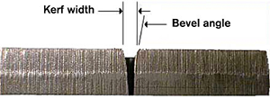
Kerf is the void created by the plasma cutting process, or the amount of metal removed by the plasma arc. The plasma arc is dynamic (it changes in size and shape depending on amperage, voltage, gas flow and velocity of the moving torch) and so as the plasma arc column changes so does the kerf. Nozzle size also has a direct affect on kerf width since the nozzle orifice constricts the plasma gas jet to a particular diameter. (Nozzles are sized according to amperage rating: the bigger the hole the more power it can handle.) A good rule of thumb for estimating the kerf width is to multiply the nozzle orifice size by a factor of 1.5. For example a 200 amp air nozzle with an orifice of .086", will have a kerf width of approximately .129".
CNC controls for plasma arc cutting have an adjustable parameter called kerf compensation. The operator or programmer enters a value for kerf compensation that is usually equal to the kerf width, (some controls use _ the kerf width). The CNC then automatically calculates to compensate for the width of the cut, keeping the kerf on the waste side of the part. To find the proper kerf compensation value, operators often use a trial and error method. They first estimate the kerf using the rule of thumb or physically measure it to get an initial value. They then cut test pieces, measure them, adjust the kerf compensation up or down, and repeat the process until the part measures correctly.
Kerf too wide (part too small)
This problem can be caused by a worn nozzle, high torch standoff (arc voltage), excessive amperage, inadequate gas flow, or low speed. Each of these variables will cause the arc column to grow, widening the kerf. An incorrect (small) kerf compensation value will also cause an undersized part. Kerf too narrow (part too big). This problem can be caused by low torch standoff (arc voltage), inadequate amperage, excessive gas flow, or high speed. These variables cause the arc column to shrink, narrowing the kerf. An incorrect (large) kerf compensation value will also cause an oversized part.
Bevel angle is the angle of the cut edge
A cut with 0° bevel is a straight cut, perpendicular to the plane of the material. Most plasma torches use a clockwise swirling flow of plasma gas, which produces a straighter cut on the right hand side of the kerf with respect to forward torch motion. Typical bevel angles for conventional plasma torches range from 1-3 degrees on the "good" side of the cut and 3-8 degrees on the "bad" side of the cut. High tolerance plasma cutting systems can achieve even lower bevel angles. Although some bevel is inherent in the plasma process due to the shape of the gas jet as it exits the torch nozzle, it is possible to minimize it. Bevel angle greater than 5 degrees may indicate a problem with PAC machine parameters.
(Excessive) Positive bevel

Positive bevel - top of part smaller than bottom
This problem may be caused by a worn nozzle, high torch standoff (arc voltage), inadequate amperage, or excessive speed. All of these variables cause the arc to lag which causes more energy to contact the top of the kerf than the bottom. As a result, the kerf is wide at the top and narrow at the bottom. Improper cut direction around the part may also cause excessive positive bevel angle. A part with excessive positive bevel all around it may also have a hard bead of high-speed dross at its bottom edge.
Negative bevel

Negative bevel - bottom of part smaller than top, undercutting
This problem can be caused by low torch standoff (arc voltage), excessive amperage, or low speed. These parameters cause the arc to remove more material at the bottom of the plate. Usually a consistent negative bevel around the part is accompanied by low speed dross.
Irregular bevel

Positive cut surface - positive and negative bevel on the same piece
This problem usually indicates that the nozzle has failed, the torch is out of square or the electrode and nozzle are misaligned. These variables cause the arc to deviate from a straight path through the material. Often one side of a square part will have a positive bevel and the opposing side a negative. The cross section of the part looks like a parallelogram rather than a rectangle. Sometimes the cut surface may not be flat, but rather concave on one side and convex on the other. These are all signs of severely worn or misaligned parts.